Package :
Standard Export Package Carton/WoodTransportation :
Express · Sea Freight · Land Freight · Air FreightDelivery Time :
5-7 Working DaysWarranty :
18 MonthsTerm of payment :
T/T, L/C, D/PSample freight payer :
BuyerSample provide :
YES| Elevator Command Call Board | ||
| Dimensions (mm) | Installation size (mm) | Installation aperture (mm) |
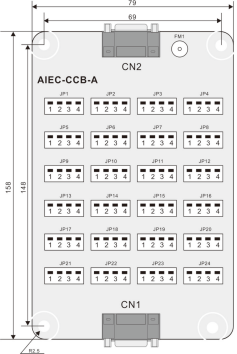
| 158*79 | 148*69 | Φ4.5 |
Feature:
● It can realize the primary and auxiliary control box buttons that in the elevator car to call the elevator.
● Support drivers, direct driving, fire fighting and independence input
● Support for overloaded buzzer alarm output
● One piece per 16 floors for cascading up to 48 levels
Description:
Car call board (AIEC−CCB) is used for the communication between the user and the control system. The main function is to collect button calls and output signals of the button call indicators. The car call board with 24 digital inputs, 22 outputs, include 16 floor buttons and 8 functional signals. The requirement of the 40−floor can be realized through cascaded connection.( CN1 is an output connector and CN2 is an input connector.)

Appearance and dimensions of the CCB (unit: mm)
|
No. |
Interface |
Pins 2 and 3 |
Pins 1 and 4 |
Terminal wiring instructions |
|
1 |
JP1 |
Floor 1 button input |
Floor 1 display output |
When the CCB is used as a cascaded CCB, the input signal of JPn corresponds to floor (16+n) button input. |
|
2 |
JP2 |
Floor 2 button input |
Floor 2 display output |
|
|
3 |
JP3 |
Floor 3 button input |
Floor 3 display output |
|
|
4 |
JP4 |
Floor 4 button input |
Floor 4 display output |
|
|
5 |
JP5 |
Floor 5 button input |
Floor 5 display output |
|
|
6 |
JP6 |
Floor 6 button input |
Floor 6 display output |
|
|
7 |
JP7 |
Floor 7 button input |
Floor 7 display output |
|
|
8 |
JP8 |
Floor 8 button input |
Floor 8 display output |
|
|
9 |
JP9 |
Floor 9 button input |
Floor 9 display output |
|
|
10 |
JP10 |
Floor 10 button input |
Floor 10 display output |
|
|
11 |
JP11 |
Floor 11 button input |
Floor 11 display output |
|
|
12 |
JP12 |
Floor 12 button input |
Floor 12 display output |
|
|
13 |
JP13 |
Floor 13 button input |
Floor 13 display output |
|
|
14 |
JP14 |
Floor 14 button input |
Floor 14 display output |
|
|
15 |
JP15 |
Floor 15 button input |
Floor 15 display output |
|
|
16 |
JP16 |
Floor 16 button input |
Floor 16 display output |
|
|
17 |
JP17 |
Door open button input |
Door open display output |
When the CCB is used as a cascaded CCB, the JP17~JP24 terminals are invalid. (When the cascaded CCB is used for back door control, JP17 can be used to implement back door open.) |
|
18 |
JP18 |
Door close button input |
Door close display output |
|
|
19 |
JP19 |
Door open delay button input |
Door open delay display output |
|
|
20 |
JP20 |
Direct travel ride input |
Non−door zone stop output |
|
|
21 |
JP21 |
Attendant input |
Reserved |
|
|
22 |
JP22 |
Direction change input |
Reserved |
|
|
23 |
JP23 |
Independent running input |
Reserved |
|
|
24 |
JP24 |
Fire emergency input |
Reserved |
|
|
Note: Pins 1 and 2 are positive of power supply. The pin with white dot mark or weld pin is rectangular is pin 1. |
||||
Note:
The AIEC−CCB has the same interfaces on both ends, and do not make wrong connection when connecting multiple boards in series.
Perform wiring strictly according to the terminal marks and ensure that the button is inserted securely.
 Request for Quotation
